
Manifolds Installation guide


Before installing the manifolds, follow this guide for tubing installation after the panel assembly.
All tubing and plumbing connections located at the manifolds are required to be installed by a licensed plumber or radiant heating contractor.
Before proceeding, carefully evaluate and tighten all fittings on the manifold to prepare the manifolds for installation. DO NOT use manifolds, fittings or repair couplers that are not supplied by Warmboard.
Minimum Framing Dimensions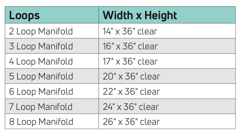
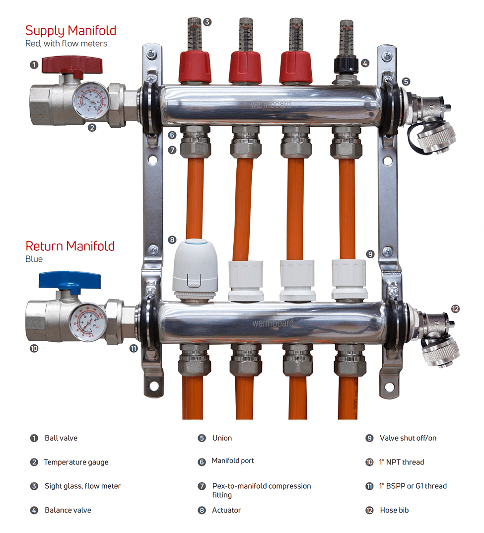
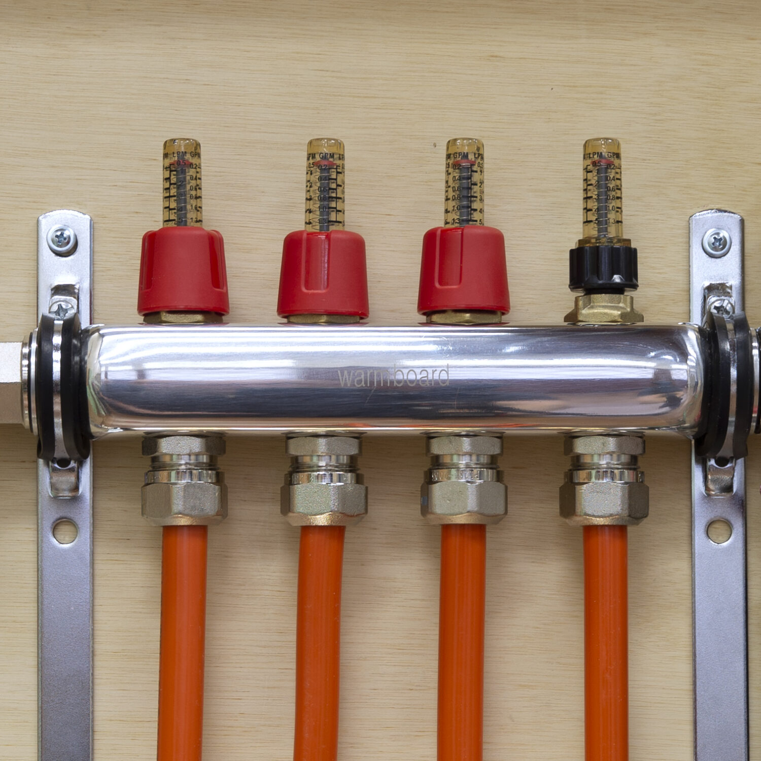
Installation Notes
-
Warmboard branded manifolds can be installed in whichever orientation best fits the install location – right side up, upside down, or sideways.
-
The manifold’s supply/return connections can come from either side.
-
While Warmboard’s radiant manifolds may fit within a 2″ x 4″ stud bay in specific applications, for ease of install, a 2″x 6″ stud bay may be the preferred location.
-
Manifolds must be accessible. Finish the installation with a simple cabinet door that can be easily accessed and opened.
-
Right angle ball valves are available to purchase with these manifolds if space is a consideration.
Manifold Installation
All tubing and plumbing connections located at the manifolds are required to be installed by a licensed plumber or radiant heating contractor.
- Now that the tubing has been run, check your layout for the manifold placement, giving enough room for the loops and supply/return ball valves to be installed.
- Mount the manifold to plywood or blocking within the stud bay. Do not mount directly to the drywall.
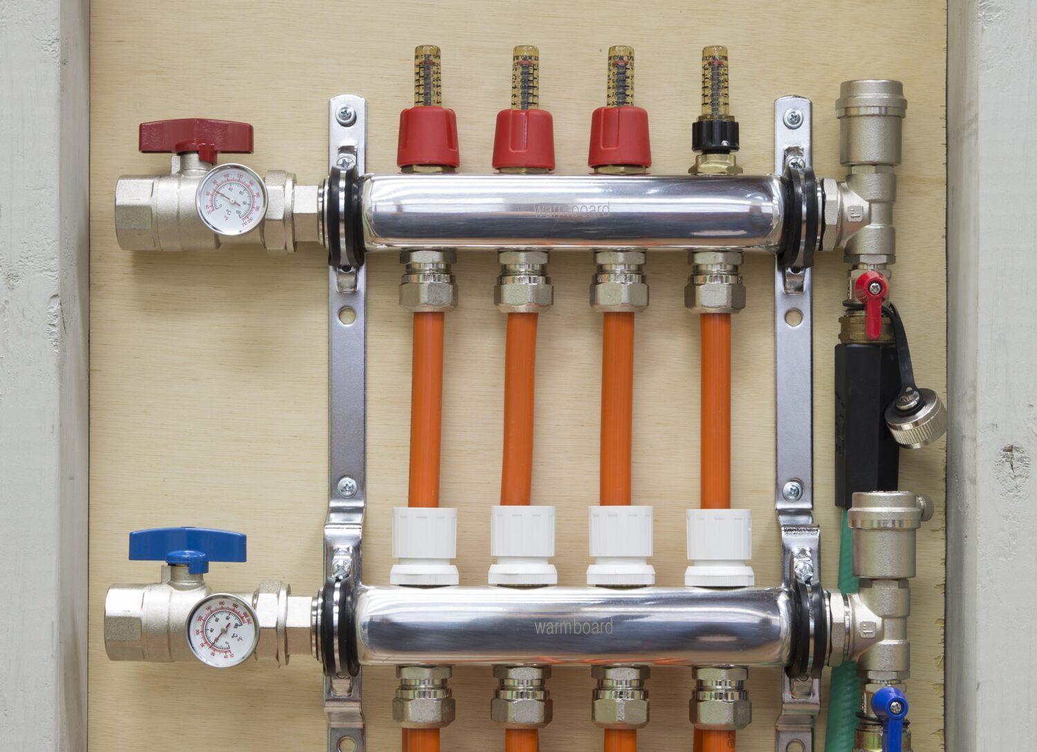
- Ensure the drain valves on the manifolds are completely closed. The cap to the drains acts as the key for the drain’s valve (hose bib).
Tubing-to-Manifold Connections
Mandatory Notes
- All PEX tubing cuts should be straight and square and made with a proper PVC cutter
- Use the chamfering tool on all PEX tubing connections before a fitting is installed
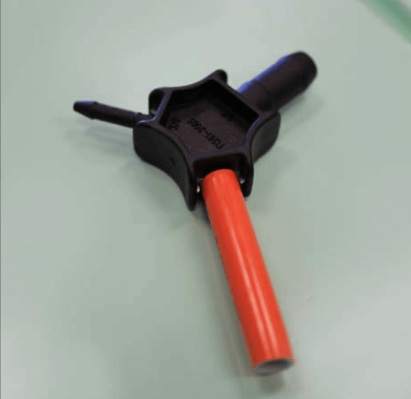
- Insert the chamfering tool completely into the tube until it bottoms out, then spin the tool to cut a beveled edge into the tubing
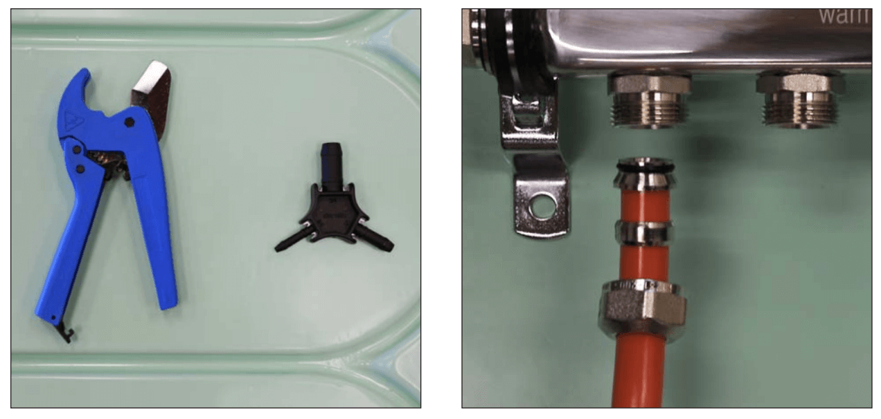
Fitting Installation
- Straighten the tubing before making a square cut with the tubing cutter.
- Use the provided stickers to label all loops at the manifold to clearly communicate the loop number and zone.
- Use the chamfering tool provided to expand and clean up the tubing. The tubing can damage O-rings if it is not chamfered.
- Install the compression fittings on each tube by first sliding the nuts and compression rings onto the tubing, then inserting the nipples into the end of the tubes.
- Firmly fasten the loops to their manifold ports, but do not use thread seal tape or pipe dope. Avoid overtightening.
More install information
Review the Warmboard-S or Warmboard-R Installation Guide for more information on tubing installation.
Pressure Testing
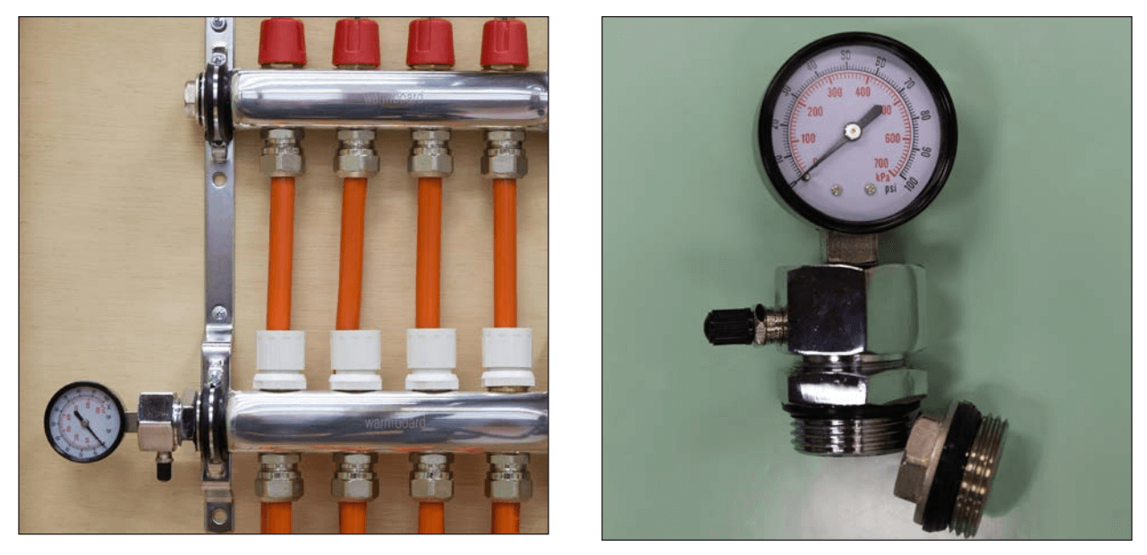
Using the test kit
- Remove both 1″ ball valves on both manifolds to expose the 1″ BSPP fittings
- Insert both the pressure gauge and end cap on the manifold and fasten securely (see images).
- Ensure gasket on the test kit is in the proper location – it must be between the lock nut and the manifold.
- The pressure test kit should seal at just above hand tight. Do not use thread seal tape or pipe dope to seal.
- Air test to the mechanical code requirement of 100 PSI for 15 minutes 6. During the rest of the construction process, keep the tubing and manifolds under pressure with 60 PSI (note: 5–10% of the air will settle and cause the PSI to drop).

Warning for Pressure Testing
- Do NOT leave tubing exposed and pressurized during winter months. Water will freeze and expand when ambient air temperatures drop below 35˚F, causing the tubing to burst.
Filling and Purging
The entire closed loop system should be filled with city or well water, and the air needs to be removed from each loop and then entire system. If air is not properly removed from each loop, the system will be noisy and could experience air locks which halts water circulation.
- Use a standard hose (fill hose), and thread on to the supply hose bib located below the manifold air vent
- Thread another standard hose (discharge hose), on the hose bib located below the other air vent. Make sure the other end of this hose is outside the home so water can drain properly
- Open the large blue and red ball valves located next to the temperature gauges. This will allow the water to circulate from the supply and return distribution lines
- Remove all red plastic flow meter covers on the supply manifold to access the balance valve flow adjustment for each loop
- Turn the black knob located below each sight glass clockwise until the balance valve is completely closed and no water can flow through
- With all balance valves closed, turn the spigot on and circulate water through the manifolds.
- Keep the water running until all air has been discharged from both hoses and the manifolds. When complete, turn off the ball valves located below the air vents
- Turn a black knob (counterclockwise) on only one loop to the fully open position to adjust flow
- Continue filling and flushing this loop with water by opening the ball valves and witnessing air burping from the discharge hose. After several minutes, no more air will discharge and you can shut off the ball valves located below air vents
- Continue this process for each loop to purge all air
- If installing Warmboard Comfort System, refer to the WCS Installation Guide to complete the steps shown on this page.
Manifold Supply / Return
As shown in the plan set, the supply and return distribution lines for the radiant manifolds must be home run to the mechanical room.
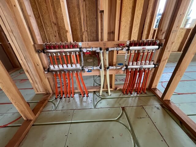
Roughing In Distribution Lines
On the Piping Layout pages of the WCS plan set, the sizes and lengths for manifold distribution lines are noted.
- Do not move manifold locations prior to consulting with Warmboard. The distance of a manifold from the boiler was used in specifying tubing size.
- While the ball valves on the Warmboard manifolds have a 1″ NPT connection, follow the piping size specified in the plan set.
- Installers may adapt the distribution piping with code compliant fittings of their choice.
- Label the supply and return lines in the rough-in stage. Be aware that use of excessive fittings can increase system headloss. Use PEX fittings sparingly as they obstruct fluid flow.