Tubing Installation Guide

Step 1: Clean the Panels
Clearing the panels and tubing channels of debris will ensure the tubing sits flush and level. This is essential to a well functioning radiant system.
- Use a broom, shop vacuum or leaf blower to clear the debris from the panel and tubing channels
- Use a 1/2″ conduit to break loose stuck-on material
Step 2: Tubing Layout
Follow the Tubing Layout in the plan set and mark the tubing paths on the panels with a permanent marker or marking paint
- Clearly label turns, bury points, and custom routes along the tubing path.
- Mark locations of all penetrations in the floor that may interfere with the tubing (toilet flanges, drains, water lines, forced air registers, etc).
- Label every loop path with the loop ID (manifold and loop number) using the loop marker icons in the WCS Plan Set.
Step 3: Manifold Layout
When laying out the manifold placement, take the tubing runs and supply/return distribution lines into account.
- Warmboard-branded manifolds can be installed in whichever orientation best fits the install location: right side up, upside down, or sideways.
- The manifold’s supply/return connections can also connect on either side.
- Mark the placement of any holes for tubing around the manifold location.
Step 4: Planning Home Runs
To run the tubing back to the manifolds, there are a few different options. The Tubing Layout will illustrate which method is used for each loop.
- Method 1
Use the existing channels in the panels to return the tubing to the manifold - Method 2
Create custom routes in the panel and return the tubing back to the manifold
- Method 3: Buried Tubing
Create a bury point and feed the tubing back to the manifold by going through the subfloor
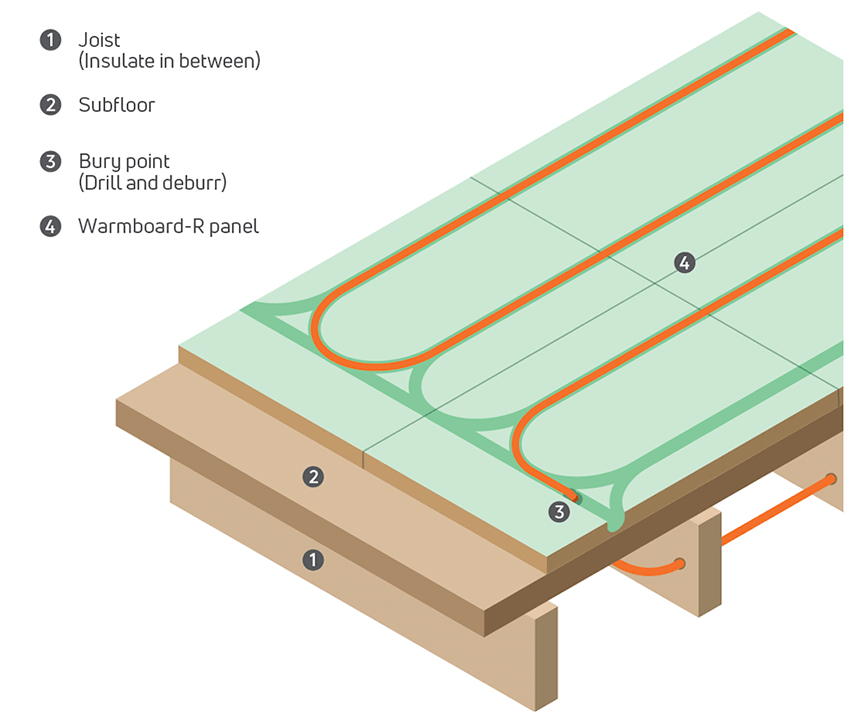
Once a method has been determined, prepare to “cut back” panels and/or drill all the bury points.
- Use a 3/4″ drill bit for your bury points. Where tubing enters the floor through a bury point, drill at a low angle or drill multiple holes side-by-side to give the tubing more flexibility in how it passes through the panel.
- A panel “cut back” can be made by either cutting out sections of panels to make space on the floor or simply moving panels out of the way.
- Reference details of the “cut backs” in your plan set and determine what type of detail works best for your installation.
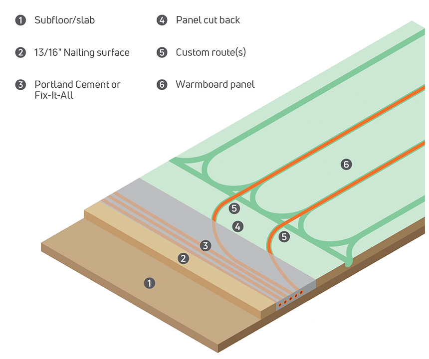
- Method 4: Panel Cut Back
Use the “panel cut back” to create a tubing channel above the slab for the tubing to return to the manifold. Fill with Portland cement to create a level surface (illustration 2)
Tips:
- Use a Sharpie or wax pencil to mark the panels.
- Use a 3/4″ drill bit to create a 3/4″ x 11/2” bury point which will help prevent the tube from kinking as it passes through the panel.
Step 5: Creating a Custom Route
Follow the instructions for selecting a router and creating a custom routes.
Tubing Installation
Installation tips
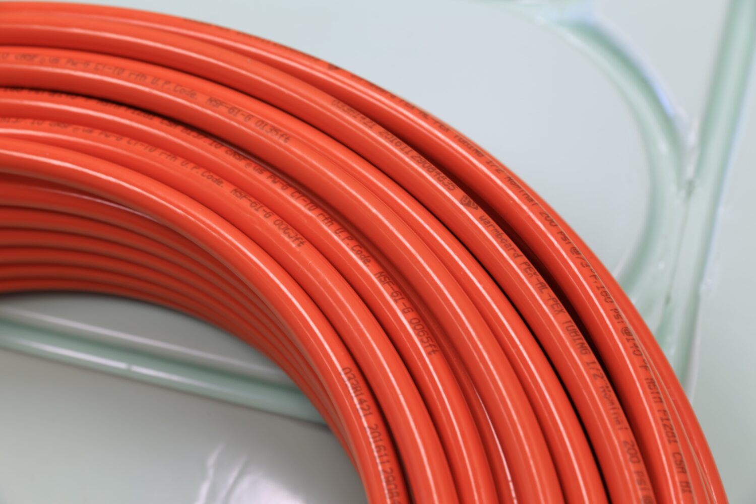
- Tubing uncoilers will help avoid twists and kinks when installing the tubing.They are an excellent investment and highly recommended for large jobs.
- Avoid installing tubing at temperatures below 50˚F as the tubing becomes rigid and difficult to bend.
- Do not use silicone or other types of adhesives in the tubing channel.
- Tape over the ends of the tubing to prevent debris from clogging the lines.
- Keep track of loops by labeling the tubing throughout the install process. Use the supplied loop labels provided in the installation kit.
- Custom routes require a router with a minimum 2 hp, though 2.25 hp is recommended. Do not attempt a custom route without the proper template and template guides (previous page).
- Do not exceed a 275 linear loop length when making field revisions.
- Use nail plates to secure tubing as needed and remove before finish floors are installed.
- After the tubing is installed, we recommend use of Masonite, Lauan or Ram Board in high traffic areas to help protect the tubing. Remove before installing the finish floors.
Buried Tubing Process
While there are several ways to install tubing, below is an example of how to bury tubing. If the loop does not have sections of buried tubing, start your installation process directly from the necessary manifold.
- Mark the end of the tubing as either the supply or return.
- Find your first bury point and measure the distance from that bury point to the manifold location.
- Measure out that distance along the length of the tubing and make a mark on the tubing with a pen. Give yourself some extra distance so that there is enough material to work with later. Note: Warmboard adds 15′ of length to each loop.
- Insert the tubing down into the bury point until the mark is reached.
- Lay the tubing into the grooves in the Warmboard, following the path that was marked out on the panels.
- Use a 16oz. rubber mallet to secure the tubing in the channel (be sure the tubing sits level and flush with the top of the panel).
- When the next bury point is reached, measure out the distance from that bury point to the manifold.
- Continue to meter-out enough tubing to reach back to the manifold, then cut the tubing. Remember to leave extra material for later.
- Insert this length of tubing into the bury point.
- Beneath the floor, route the tubing back to the manifold location. Support the tubing with straps along the way.
- Run the supply and return through the floor at the manifold location making sure the supply terminates in the back and the return terminates in the front of the manifold location.
Next up: Manifold Install guide.
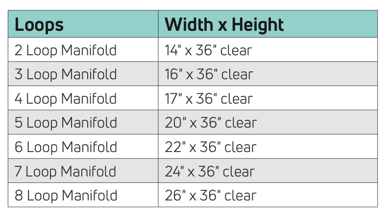
Minimum Framing Dimensions:
Tubing Repair
Every tubing manufacturer makes a repair coupler to repair a punctured section of tubing.
Other recommendations:
- The tubing must be level and flush with the surface of Warmboard.
- Consider Ram Board (or equivalent) to help protect the tubing in high traffic areas.
- Warmboard adds 15 feet of length to each loop to provide additional flexibility during the installation process.

Next, follow this guide for Custom Routing and manifold installation.
Tubing Repair
Tubing Repair instructions
Should damage occur, Warmboard offers two types of repair couplers.
All repairs MUST are done by a licensed plumber or radiant contractor.
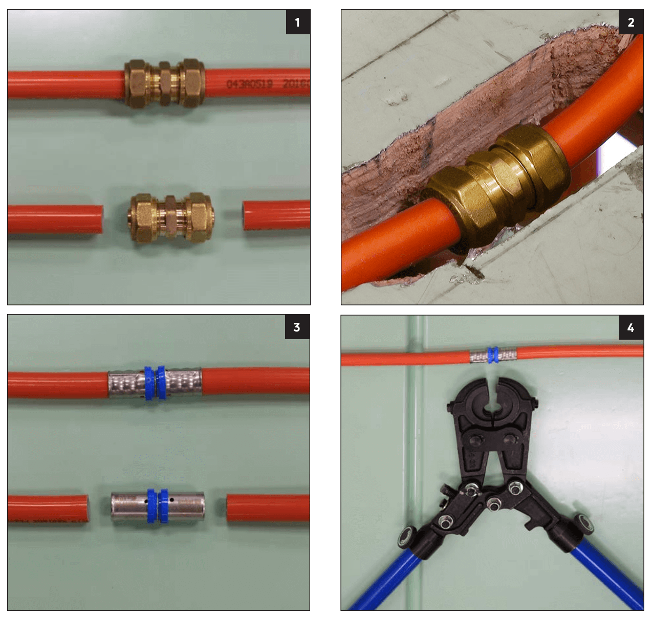
Method 1: Threaded
This fitting has an outside dimension of 1″ and uses two brass compression fittings and a brass nipple to create a repair (photo 1)
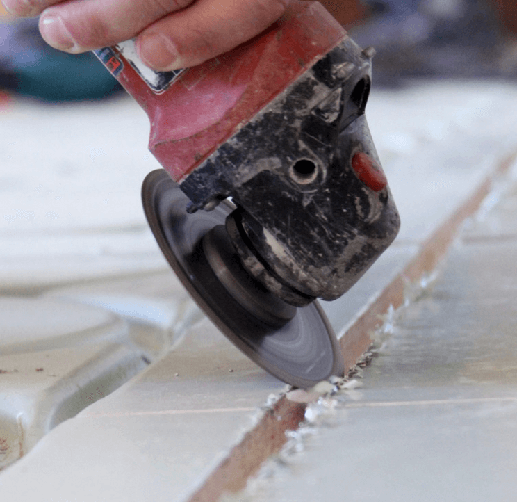
- Chisel out part of the Warmboard tubing channel to accommodate the fitting (photo 2)
- Cut the tubing square and use the chamfering tool before installing fittings. DO NOT use tape or dope on the threads
Method 2: Pressed
This stainless/brass repair coupling (photo 3) uses a permanent compression and requires the purchase of a Warmboard-supplied pressing tool (photo 4). This fitting has an outside dimension of 13 /16″.
- Chisel out part of the Warmboard tubing channel to accommodate the fitting
- Cut the tubing square and use the chamfering tool before installing fittings. DO NOT use tape or dope on the threads