
WCS Commissioning

Preparation
Before installing the controllers, be sure to turn off Construction Mode at the display on the SRC. This will turn off the pumps and boiler until the controls call for heat.
An installer must review the electrical page of your WCS Plan Set and note locations of all electrical components.
Tubing and Labeling
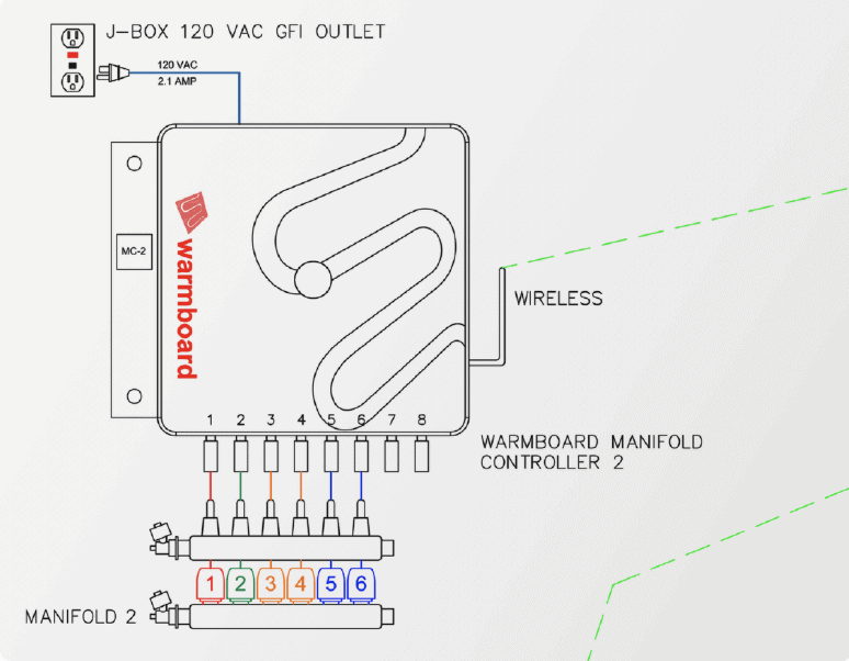
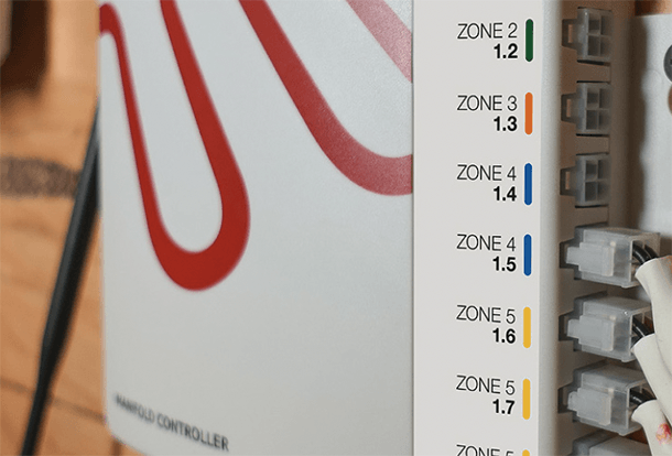
Included with your controls, was a series of labels to adhere to each supply and return loop beneath the manifold. Appropriate use of these labels will ensure each loop is accurately labeled for diagnostic issues. These color-coded labels coincide with the color labels on the side of the manifold controller (MC) and those displayed in your WCS Plan Set.
Installing the MC
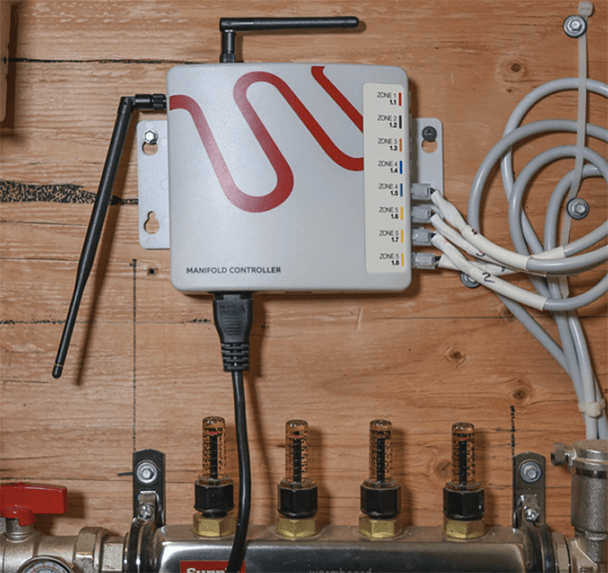
- Use the provided screws to mount each Manifold Controller (MC) inside the manifold location specified in the WCS Plan Set.
- Plug the MC into the 120 volt outlet.
Installing the Actuators
- Thread the mounting rings from each actuator onto the shoulders of the valves on the manifold.
- Attach actuators to each port on the return manifold.
- Connect each actuator wire to the appropriate port on the side of the MC, which is pre-labeled and color coded. Refer to the WCS Plan Set as needed.
- For the system to run in normal operation, you must disable Construction Mode through the display on the SRC.
Thermostat installation
System Start-up
Prior Steps
It is imperative that all previous tasks have been completed before testing or operating the system.
- Use of Construction Mode to test the boiler and adjust flow rates on each loop.
- Disable Construction Mode from the SRC display.
- If Warmsource has operated in Construction Mode near any dust or debris, service and clean the heat exchanger prior to normal operation.
- Successful installation of all electrical components (manifold controllers, actuators, thermostats).
Once these steps have been completed sequentially, reset the Warmsource power and proceed to the next steps.
SRC Display
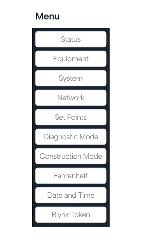
While it is not required to use the SRC interface for system start-up, the following menu items may be useful in confirming system setup and connectivity.
- Status: Check boiler set points, water temperatures, error codes, and valve states across the entire system.
- System: Confirm device count and check firmware versions on all equipment in the system.
- Network: Confirm the network configuration and test signal reliability of the LoRa and Wi-Fi networks.
- Setpoints: Adjust important water and room temperature settings for the system. Note: this may impact the overall performance of the system.
- Turbo Mode Water Temp: This is the temperature of the water supplied to the system when a zone is 5°F degrees from set point or when a zone is slow to heat.
- Boiler Max Water Temp: This is the maximum water temperature that will be called in normal heating operation outside of Turbo Mode.
- When Warmboard thermostats are set to Off, they will maintain a minimum temperature of 55°F by default.
System tests
Prior Steps
It is imperative that all previous tasks have been completed before testing or operating the system.
- Use of Construction Mode to test the boiler and adjust flow rates on each loop.
- Disable Construction Mode by removing the jumper from the appropriate sensor port.
- If Warmsource operated in Construction Mode near any dust or debris, service and clean the heat exchanger before beginning normal operation.
- Successful installation of all electrical components (manifold controllers, actuators, thermostats).
Once these steps have been completed sequentially, proceed to the next steps.
Testing Communication
Before testing the zones independently, verify that the system components are communicating. To do this, complete the following steps in the SRC:
- In the Network menu, tap Signal Reliability.
- On the next screen select LoRa Test.
- Reference the test results and check on any of the pieces of equipment which are not communicating
- Check for power to the units.
- Check that antennas are completely attached.
Testing the Controls
With all components installed, it’s time to test each zone independently to ensure the thermostats are accurately controlling each zone.
- To begin, go to the zone 1 thermostat, then follow the instructions below.
- Tap the thermostat screen.
- Next, tap the Menu icon ☰ in the upper right corner and to enter the main menu. Click the Information icon to familiarize yourself with the menu.
- Once complete, go to Settings, then System Tests and tap Test Zone.
- Go to the manifold cabinet for this zone. On the manifold controller you will see a red light on the loops requesting a call for heat.
- After 5 minutes, the red lights will turn green, indicating that the actuators have opened and water is flowing to the zone.
- If something does not appear to be working properly, consult your WCS Plan Set.
- After 15 minutes, the test will end.
- Repeat this process for each thermostat. and tap Test Zone.
- Go to the manifold cabinet for this zone. On the manifold controller you will see a red light on the loops requesting a call for heat.
- After 5 minutes, the red lights will turn green, indicating that the actuators have opened and water is flowing to the zone.
- If something does not appear to be working properly, consult your WCS Plan Set.
- After 15 minutes, the test will end.
Repeat this process for each thermostat.
- Make sure all supply and return tubing labels have been affixed to the appropriate loop at the manifold location.
- When a zone calls for heat, the actuators will take roughly 5 minutes to open and begin heat flow.
- Warmboard thermostats have an default Off setting of 55˚F for freeze protection.
Final Checks: Wi-Fi Connections
Wi-Fi connectivity is an important feature as it allows the user to access their system through our mobile application and allows the system to receive important software updates.
- Perform the LoRa communication test from the SRC, which is described on the previous page.
- Note which thermostat has the best communication with the SRC and proceed to that thermostat’s location.
- Tap the thermostat screen, then tap the menu icon ☰ icon.
- Choose Settings, then Connectivity.
- Follow the prompts to connect to the local Wi-Fi.
- Return to the SRC to verify that the Wi-Fi Network on the Network page matches the local Wi-Fi Network.
- If network connectivity issues arise while commissioning, resetting the power to the thermostats, MCs and SRC is an ideal way to reinitialize the system’s communication. This can be done using Diagnostic Mode on the SRC.
Water Temperature Chart
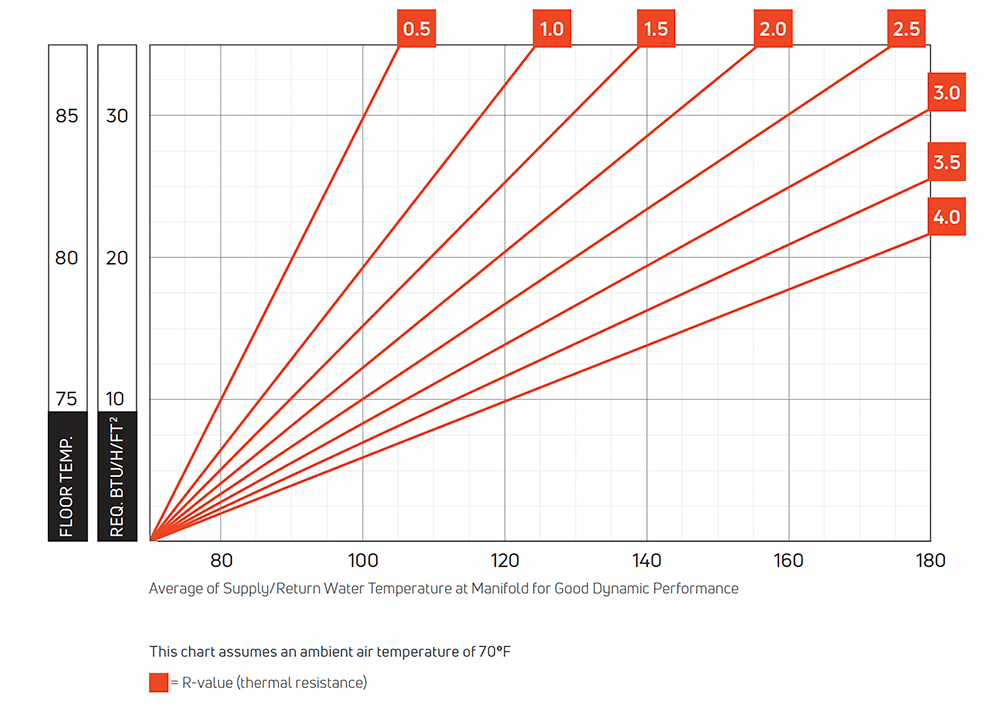
Steady State performance requires 10% lower water supply temperature.
Assumes minimum R-19 insulation below the floor.
Go back to WCS install guide.