Construction Mode

installation guide

Construction Mode is a control loop in which the primary pump, secondary pump, and boiler run without the Warmboard Comfort System thermostats or manifold controllers.

Once the system is properly filled, use Construction Mode to heat the structure before thermostats, MC(s), and actuators are installed.

Warmboard SRC menu screen


Construction Mode offers the opportunity to:

  • Remove air from the system.
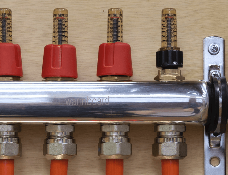
  • Balance and set flows rates.
  • Heat an active job site and hasten the release of moisture from building materials:
    • Paint
    • Plaster
    • Hardwood flooring
    • Other wood materials

Boiler Start-Up with Construction Mode

  1. Remove the doors for both the upper and lower cabinets.
  2. In the upper cabinet, locate the gas valve and turn the gas valve’s switch to the On position.
  3. Plug the Warmsource into its designated outlet. The display on the SRC in the lower cabinet will start up and display the main menu.
  4. In the menu, navigate to Construction Mode.
  5. Select a supply water temperature and your preferred control option (Timed or Thermostat) before turning on Construction Mode. You cannot adjust these settings while Construction Mode is running.

Timed

This setting allows the system to modulate heat output by reducing the run time of the boiler. In this mode, the desired Heating and Idle times can be set. The unit will cycle between Heating and Idle once Construction Mode is turned on. If Idle is set to zero, Construction Mode will heat indefinitely.

Thermostat

In this mode a dry contact thermostat can be wired to the bottom two terminals of the port labeled Sensor:

  • Construction Mode must be turned off before any settings can be changed.
  • Every Warmsource is pre-set at our factory to maintain proper temperature control and operation.Do not adjust.
  • Purge all air from the gas line before firing. You must use a combustion analyzer in Construction Mode.
  • Do not use Construction Mode after actuators are installed.
  • If operating the Warmsource during Construction Mode, you must keep the venting clear of dust and debris. Be sure to service and clean the heat exchanger prior to normal operation. Failure to do so could cost hundreds of dollars in repair fees.

Combustion Analysis

It is required that combustion is adjusted with a Combustion Analyzer while in Construction Mode. Combustion values must match those listed in the Lochinvar manual (Chapter 10: Start-up, table 10A).

Failure to do so may shorten the life of the boiler and could result in injury or death.

Setting Flow

In order for the system to heat evenly and maintain the proper temperatures on design day conditions, flow rates must be set at the manifolds.

The ideal time to adjust the flow rates is during Construction Mode, before the controls are installed, when all loops open and flowing.


Suggested Process for Setting Flow

Before setting flow, remove the red sleeves from the balance valves on every manifold and ensure the balance valves are fully open (three turns counter-clockwise [CCW] from the closed position). Once done, follow these steps starting at the manifold location closest to the Warmsource:

  1. Reference the Radiant Design Data in the WCS Plan Set for the specified flow rates.
  2. Adjust each balance valve until the flow meter registers the designed flow rate. Avoid touching the sight glass and turn CW to close and CCW to open. The red plunger in the flow meter should sit at the mark which corresponds to the specified flow rate.
  3. Once the manifold has been completely adjusted, move to the next closest manifold to repeat the process.
  4. When all the manifolds have been adjusted, perform a walk through on all adjusted manifolds. Readjust flows where they may have changed during the process and replace the red caps onto the balance valves.

Listed flow rates are minimum values. It is acceptable to increase flow rates in a zone as long as all loops increase flow relative to each other in that zone.

To set flow on a system with manifold controllers installed, use the Open All Loops command in conjunction with the Secondary Pump relay control in Diagnostic Mode.

Diagnostic Mode

Diagnostic Mode is a simple control loop which allows a technician to directly control the relays and valves on the SRC. This can be used to verify relays, confirm certain components are functioning, and reset the SRC.

Running Diagnostic Mode

  1. Tap the screen on the SRC, then scroll to and tap
    Diagnostic Mode.
  2. Press the grey Power icon next to Start Diagnostic
    Mode. The icon will turn green.
  3. Actuate relays by toggling the corresponding icons on and off. Avoid running the secondary pump without open loops in the system.
  4. Once done, turn off Diagnostic Mode by pressing the Power icon again.

  • Avoid dead heading the secondary pump for extended periods of time.
  • After an hour of inactivity, the SRC will exit Diagnostic Mode.